
Ford Aerostar camshaft removal and installation - is a part of Ford Aerostar repair manuals: Engines. This part contains the detailed description and diagrams for Ford Aerostar with 2.3l, 2.9l, 3.0l and 4.0l engines.
Ford Aerostar camshaft removal:
Rotate crankshaft to 0 degrees at Top Dead Center (TDC) on the compression stroke. Disconnect negative battery terminal and set aside. Drain engine cooling system. Remove PCV closure hose from rocker arm cover and clean air flex tube. Remove clean air flex tube from throttle body and air cleaner. Carefully relieve fuel pressure at fuel supply manifold schrader valve as outlined in Ford Aerostar repair manuals: Fuel Charging and Controls. Mark location of vacuum lines and remove. Disconnect ACT, TPS, BPA, ISC, ECT, distributor, ignition coil and coolant temperature sending unit electrical connectors. Disconnect upper radiator hose from thermostat housing. After loosening retaining clamp, use a twisting motion on hose to loosen from housing. Disconnect and remove heater hoses.
 Remove throttle body as outlined in Ford Aerostar repair manuals: Fuel Charging and Controls. Disconnect fuel injector harness retaining stand-offs from inboard rocker arm cover studs. Carefully disconnect electrical connections to each injector and remove harness from engine. Remove ignition wires from spark plugs by using a twisting motion on the rubber boot. Remove harness retaining stand-offs from rocker arm cover studs. Mark distributor housing to block and note rotor position. Remove distributor retaining bolt and washer. Remove distributor.
Remove ignition coil from rear of left cylinder head. Remove rocker arm covers as outlined in this section. Loosen cylinder No. 3 intake valve rocker arm retaining nut and rotate arm off of push rod and away from top of valve stem. Remove push rod. Remove alternator assembly, brackets and belt tensioner and belt. Remove intake manifold retaining bolts using a Torx head socket. Before attempting to remove intake manifold, break the seal between the manifold and cylinder block. Wedge a large screwdriver or similar heavy-duty tool between the manifold and the block. Pry upward on the tool using the lug on top of the front cover as a leverage point. Loosen rocker arm fulcrum retaining bolts enough to allow the rocker arm to be lifted off the push rods and rotated to one side. Remove push rods. Identify each push rod's location. The push rods should be installed in their original location and position during reassembly. Loosen roller tappet guide plate retainer bolts (2). Remove guide plate retainer assembly from tappet valley. Remove tappet guide plates from tappets by lifting straight up. Remove tappets by grasping each tappet and pulling in line with bore. Remove radiator, shroud and air conditioner condenser (if so equipped). Remove cooling fan assembly. Loosen water pump pulley retaining bolts while accessory drive belt is tensioned. Loosen power steering pump drive belt tensioner and remove belt. Rotate power steering belt tensioner bracket up and out of the way. Finish removing water pump pulley retaining bolts and remove pulley. Remove air conditioner compressor from bracket (4 bolts, if equipped). Wire tie compressor out of the way. Remove air conditioner bracket from front cover and cylinder block (if equipped - 3 bolts, 2 nuts). Remove four crankshaft pulley retaining bolts and remove pulley. Remove crankshaft damper retaining bolt and washer. Remove damper using Crankshaft Damper Removal Tool T58P-6316-D and Vibration Damper Remover Adapter T82L-6316-B or equivalent. Remove lower radiator hose. Remove auxiliary heater supply tube bracket nut from water pump retaining stud. Loosen or remove lower retaining bolt and move assembly out of the way (if equipped). Remove oil pan assembly as outlined in this section. Discard old gasket.
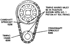
Remove front cover assembly retaining bolts. Remove front cover and discard old gasket. Place a dull, thin bladed screwdriver or similar device between front cover and cylinder block and tap to break seal. Walk front cover off cylinder block locating dowels using a soft rocking motion. Use crankshaft seal protector if available. Align marks on camshaft and crankshaft gears as illustrated.
Check camshaft end play as outlined in Ford Aerostar repair manuals: Engine Service, Gasoline. If clearance is excessive, replace camshaft thrust plate. Check timing chain deflection as outlined in Ford Aerostar repair manuals: Engine Service, Gasoline. Replace timing chain and sprockets if deflection is excessive. Remove camshaft sprocket retaining bolt and washer. Remove timing chain and sprockets. Using one hand on the camshaft sprocket and the other on the crankshaft gear, pull assembly forward and off of crankshaft and camshaft. Remove the two camshaft thrust plate retaining bolts and thrust plate. Carefully remove by pulling slowly toward front of engine keeping camshaft perfectly in line with camshaft bores. Damage to camshaft bearings and/or camshaft can occur if camshaft is allowed to drop on bearing surface or cylinder block.
Remove throttle body as outlined in Ford Aerostar repair manuals: Fuel Charging and Controls. Disconnect fuel injector harness retaining stand-offs from inboard rocker arm cover studs. Carefully disconnect electrical connections to each injector and remove harness from engine. Remove ignition wires from spark plugs by using a twisting motion on the rubber boot. Remove harness retaining stand-offs from rocker arm cover studs. Mark distributor housing to block and note rotor position. Remove distributor retaining bolt and washer. Remove distributor.
Remove ignition coil from rear of left cylinder head. Remove rocker arm covers as outlined in this section. Loosen cylinder No. 3 intake valve rocker arm retaining nut and rotate arm off of push rod and away from top of valve stem. Remove push rod. Remove alternator assembly, brackets and belt tensioner and belt. Remove intake manifold retaining bolts using a Torx head socket. Before attempting to remove intake manifold, break the seal between the manifold and cylinder block. Wedge a large screwdriver or similar heavy-duty tool between the manifold and the block. Pry upward on the tool using the lug on top of the front cover as a leverage point. Loosen rocker arm fulcrum retaining bolts enough to allow the rocker arm to be lifted off the push rods and rotated to one side. Remove push rods. Identify each push rod's location. The push rods should be installed in their original location and position during reassembly. Loosen roller tappet guide plate retainer bolts (2). Remove guide plate retainer assembly from tappet valley. Remove tappet guide plates from tappets by lifting straight up. Remove tappets by grasping each tappet and pulling in line with bore. Remove radiator, shroud and air conditioner condenser (if so equipped). Remove cooling fan assembly. Loosen water pump pulley retaining bolts while accessory drive belt is tensioned. Loosen power steering pump drive belt tensioner and remove belt. Rotate power steering belt tensioner bracket up and out of the way. Finish removing water pump pulley retaining bolts and remove pulley. Remove air conditioner compressor from bracket (4 bolts, if equipped). Wire tie compressor out of the way. Remove air conditioner bracket from front cover and cylinder block (if equipped - 3 bolts, 2 nuts). Remove four crankshaft pulley retaining bolts and remove pulley. Remove crankshaft damper retaining bolt and washer. Remove damper using Crankshaft Damper Removal Tool T58P-6316-D and Vibration Damper Remover Adapter T82L-6316-B or equivalent. Remove lower radiator hose. Remove auxiliary heater supply tube bracket nut from water pump retaining stud. Loosen or remove lower retaining bolt and move assembly out of the way (if equipped). Remove oil pan assembly as outlined in this section. Discard old gasket.
Remove front cover assembly retaining bolts. Remove front cover and discard old gasket. Place a dull, thin bladed screwdriver or similar device between front cover and cylinder block and tap to break seal. Walk front cover off cylinder block locating dowels using a soft rocking motion. Use crankshaft seal protector if available. Align marks on camshaft and crankshaft gears as illustrated.
Check camshaft end play as outlined in Ford Aerostar repair manuals: Engine Service, Gasoline. If clearance is excessive, replace camshaft thrust plate. Check timing chain deflection as outlined in Ford Aerostar repair manuals: Engine Service, Gasoline. Replace timing chain and sprockets if deflection is excessive. Remove camshaft sprocket retaining bolt and washer. Remove timing chain and sprockets. Using one hand on the camshaft sprocket and the other on the crankshaft gear, pull assembly forward and off of crankshaft and camshaft. Remove the two camshaft thrust plate retaining bolts and thrust plate. Carefully remove by pulling slowly toward front of engine keeping camshaft perfectly in line with camshaft bores. Damage to camshaft bearings and/or camshaft can occur if camshaft is allowed to drop on bearing surface or cylinder block.
Ford Aerostar camshaft installation:
Clean mating gasket surfaces of intake manifold and cylinder head. Lay a clean cloth or shop rag in the tappet valley to catch any gasket material. After scraping, carefully lift cloth from tappet valley preventing any particles to enter oil drain holes or cylinder head. Use a suitable solvent to remove old rubber sealant. Clean gasket mating surfaces of front cover to cylinder block and oil pan to cylinder block. Inspect camshaft bearings for wear. Replace as outlined in Ford Aerostar repair manuals: Engine, Service, Gasoline.
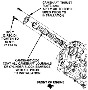 Clean and inspect all components before installation. Lubricate camshaft lobes and bearing surfaces liberally with Oil Conditioner D9AZ-19579-CA or equivalent. Lubricate distributor drive gear with ESP-M2C154-A or equivalent heavy weight gear lube. Carefully slide camshaft through bearings into cylinder block remembering to keep camshaft perfectly in line with front bearing. Lubricate camshaft thrust plate with Oil Conditioner and install with two retaining bolts. Tighten bolts to 10 N-m (7 ft-lb). If installing a new camshaft, check end play as specified in Ford Aerostar repair manuals: Engine Service, Gasoline. If clearance is excessive, replace camshaft thrust plate. Lubricate timing chain and sprockets with Oil Conditioner and install as an assembly. Align marks as illustrated. Inspect camshaft sprocket bolt for blockage of drilled oil passages and clean as required. Install bolt and washer and tighten to 50-70 N-m (41-52 ft-lb). Lubricate tappets and bore with Oil Conditioner D9AZ-19579-CA (ESR-M99C80-A) or equivalent heavy engine oil. Install tappets into original bores. Aligning tappet flats, install tappet guide plate. Install guide plate retainer assembly over guide plates. (NOTE: Retainer orientation is not important.) Hand-start two retaining bolts. Tighten bolts to 12 N-m (9 ft-lb). Apply a 5-6mm drop of Rubber Sealer D6AZ-19562-AA or -BA or equivalent to intersection of cylinder block and cylinder head assembly at four corners as shown in the illustration. Position intake gaskets onto cylinder heads. Align the intake gasket locking tabs to the provisions on the cylinder head gaskets as shown in the illustration. Install front and rear intake manifold seals as shown in the illustration. Secure with retaining features. Carefully lower intake manifold into position aligning manifold bolt holes to those in the cylinder head. Use care to prevent disturbing the rubber sealer which can cause sealing voids. Install bolts 1, 2, 3 and 4 and hand-snug. Install remaining bolts and torque in a two-step process.
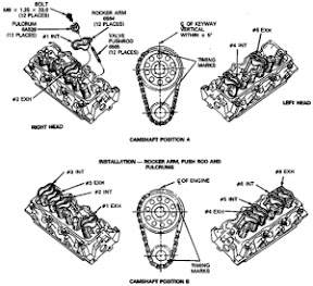
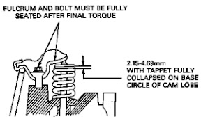 Tighten in numerical sequence to 15 N-m (11 ft-lb), then again to 26 N-m (19 ft-lb). Completely coat distributor gear teeth with ESE-M2C123-A or equivalent heavy weight gear lube. Install distributor and align to premarked location on cylinder block and rotor position. Install retaining bolt and washer and hand-snug. Apply ESE-M2C39-F oil to removed push rods and rocker arms. Install push rods. Move rocker arms into position with push rod and valve stem. Rotate crankshaft to align camshaft and crankshaft timing marks as illustrated to position A. Tighten retaining bolts of specified rocker arms to 11 N-m (8 ft-lb) to seat fulcrums into cylinder head. Rotate crankshaft to position B. Tighten retaining bolts of remaining rocker arms to 11 N-m (8 ft-lb). Final-tighten bolts to 32 N-m (24 ft-lb) in any position. If new tappets are being installed, check collapsed tappet gaps as outlined in «Section 03-00» using positions A and B. Inspect front cover crankshaft oil seal for damage and replace if required. Install new front cover gasket over alignment dowels on cylinder block. Install front cover and tighten retaining bolts to 20-30 N-m (15-22 ft-lb). Install water pump and new gasket if removed. Install new oil pan gasket to cylinder block and secure with Gasket and Trim Adhesive D7AZ-19B508-AA (ESR-M11P17-A and ESE-M2G52-A) or equivalent. Make sure the gasket retaining tab features are properly installed on cylinder block, rear main bearing and front cover. Install oil pan and all retaining bolts. Tighten four corner bolts to 10-14 N-m (7-10 ft-lb) and then the remaining bolts to the same value. Back off all 16 retaining bolts and retighten to 10-14 N-m (7-10 ft-lb). Install crankshaft damper and pulley as outlined in this section. Install rocker arm covers as outlined in this section. Install fuel injector electrical harness to each injector. Secure with stand-offs to inboard rocker arm cover studs. Install ignition coil to rear of left cylinder head.
 Tighten retaining bolts to 48 N-m (35 ft-lb). Connect electrical connector to coil. Install throttle body assembly and new gasket as outlined in Ford Aerostar repair manuals: Fuel Charging and Controls. Install ignition coil. Tighten retaining nuts to 18 N-m (13 ft-lb). Install distributor cap and ignition wires. Install wire harness stand-offs to rocker arm cover studs and connect wires to spark plugs and ignition coil. Install fuel lines to fuel supply rail as outlined in Ford Aerostar repair manuals: Fuel Charging and Controls. Install fuel line safety clips. Install air conditioner bracket to cylinder block. Tighten three retaining bolts to 41-60 N-m (30-45 ft-lb) and two nuts to 20-30 N-m (15-22 ft-lb). Install air conditioner compressor to bracket (if equipped). Tighten four retaining bolts to 41-60 N-m (30-45 ft-lb). Install alternator brackets to right cylinder head. Tighten retaining bolts to 40-55 N-m (30-40 ft-lb). Install alternator. Install auxiliary heater supply tube and bracket assembly. Tighten nut and bolt to 20-30 N-m (15-22 ft-lb) if equipped. Install water pump pulley. Hand-snug four retaining bolts. Rotate power steering belt tensioner into position. Install accessory drive belts and tension as outlined. Tighten water pump pulley bolts to 25 N-m (19 ft-lb). Install cooling fan assembly as outlined. Install air conditioner condenser, radiator and shroud. Connect radiator and heater hoses. Make sure tension clamps are positioned correctly. Connect vacuum lines to premarked locations. Connect electrical connections to ACT, TPS, BPA, ISC, ECT, distributor, ignition coil and coolant temperature sending unit. Fill and bleed cooling system with specified coolant and proper mixture. Fill crankcase with specified amount and viscosity of oil. Install clean air flex tube to throttle body and air cleaner. Tighten retaining clamps to 1.9 N-m (16 in-lb). Install PCV closure hose to rocker arm cover and clean air flex tube provisions. Connect negative battery terminal. Start engine and check for coolant, oil fuel and vacuum leaks. Verify and correct default base initial engine timing to 10 degrees BTDC. Refer to the Ford Aerostar repair manuals: Powertrain Control/Emissions Diagnosis Manual. Tighten retaining bolt to 24 N-m (18 ft-lb).
from Ford Aerostar repair manuals