
Ford automatic transmission A4LD assembly - is a part of Ford repair manuals: Manual and Atomatic Transmissions. This part contains the detailed description of assembly works and all necessary transmission diagrams for Ford Aerostar, Ranger and Explorer automatic transmission A4LD.
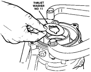
Before beginning assembly of the transmission, the following high clutch seal sizing procedure must be performed. Install new high clutch seals on the support hub. It is necessary to size these seals. The seal grooves have a "dovetail" contour with straight sidewalls on the pressure sealing sides. If this is not done, the seals can be cut or rolled over when entering the intermediate brake drum cavity. Apply a liberal amount of petroleum jelly to the center support hub and seals. Use overdrive brake drum as sizing tool. Carefully rotate the center support while inserting.Observe the seals as they enter the cavity to see that they do not roll over or get cut. Be sure the center support is seated fully into the overdrive drum. Allow to stand for several minutes so that the seals seat in the grooves. Set aside until required for reassembly later in this section. Place thrust washer No. 11 (7B368) into back of case.
 |
 |  |
 |
 |  |  |
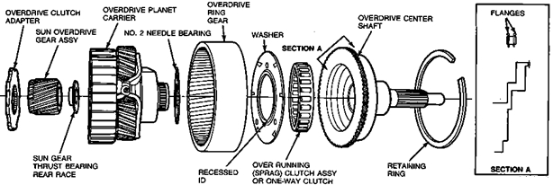
Make sure correct band is installed as identified by a tag during disassembly. Install anchor strut. Verify that needle bearing race in overdrive planetary is centered and overdrive clutch is fully seated. Place selective washer No. 1 (7D014) on top of overdrive clutch drum and temporarily install pump assembly into case. Be sure that it is fully seated in the case. The pump body must be below the level of the case gasket in the case. Mount Dial Indicator D78P-4201-G or equivalent on the pump with plunger resting on the transmission housing. Set dial indicator to zero. Swing indicator around so plunger contacts the pump. Check dial reading. This reading is the amount of end play. Note reading for later use. Move dial indicator block to opposite side of the pump (180 degrees). Repeat Steps 56 and 57. Find average of two readings. This average reading of end play should be from 0.18mm to 0.64mm (0.007 to 0.025 inch). If reading exceeds the limits, change No. 1 selective washer. Install a new hydraulic pump oil seal using Front Pump Alignment Set T74P-77103-X and Front Pump Seal Replacer T87L-77248-AH or equivalent. Stake the seal in place with tool T87L-77248-BH in two places between the existing stakes. Properly position separator plate on converter housing. Properly position two pump gears into pump housing. The inside edge of the small gear has a chamfer on one side. This chamfer must be positioned toward the front of the transmission. The larger gear has a dimple on one side which must be positioned toward the rear of the transmission. Position pump assembly onto separator plate and converter housing. Install bolts finger-tight. Note that the pump assembly stator-end face has a depression. This is completely interchangeable with flat stator-end face. Align pump in converter housing using Front Pump Alignment Set T74P-77103-X or equivalent. This tool must be used in order to prevent seal leakage, gear noise, pump breakage or bushing failure. To use tool, select the arbor with the smallest inside diameter that will fit completely over the pump shaft. Assemble the common handle to the selected arbor and slide the tool down over the shaft until it bottoms against the pump. The outside diameter of the tool arbor will then automatically center the pump in the converter housing. With alignment tool installed, tighten five new 6mm hex Allen-head pump bolts (E804375-S72M) to 22-28 N-m (16-21 ft-lb). Remove alignment tool. Insert the input shaft into the pump and install the converter into the pump gears. Rotate the converter to check for free movement, then remove the converter and input shaft. Coat converter housing gasket with petroleum jelly and position on housing. Install seal on converter housing. Using petroleum jelly, position No. 1 selective washer on rear of pump.
 Align converter housing and pump to the transmission. Install eight 17mm bolts, with new O-rings, and tighten to 36-52 N-m (27-39 ft-lb). Adjust overdrive band: install new locknut on adjusting screw, but do not tighten; using Band Adjusting Torque Wrench T71P-77370-A or equivalent tighten adjusting screw until wrench clicks. This is 14 N-m (10 ft-lb); back off adjusting screw exactly two turns; hold adjusting screw from turning and tighten locknut to 41-61 N-m (35-45 ft-lb). Following the previous method, adjust the intermediate band backing off the adjusting screw two turns before tightening the locknut. Install shift lever oil seal using Shift Lever Seal Replacer T74P-77498-A or equivalent. Install internal shift linkage, including external manual control lever, and centering pin. Tighten 7/8-inch nut to 41-54 N-m (30-40 ft-lb). Install O-ring, kickdown lever and 13mm nut. Tighten to 10-11 N-m (7-15 ft-lb). Install neutral start switch using Neutral Start Switch Socket T74P-77247-A "Thin Wall" socket or equivalent. Tighten to 10-14 N-m (89-123 in-lb). Install converter clutch solenoid connector. Install throttle valve, rod, vacuum diaphragm, retaining clamp and bolt. Be sure the throttle valve moves freely in its bore. Use a pencil magnet to check movement if throttle valve is steel. If throttle valve is aluminum, use the end of a rubber object to check movement. Align valve body to separator plate and gasket using tapered punches. Install two 10mm bolts. Tighten to 6.0-8.0 N-m (53-71 in-lb). Apply a small amount of petroleum jelly in four or five places to separator plate-to-transmission case gasket to hold in place. Position gasket on assembled separator plate and valve body. Remove transmission from holding fixture and place on bench bottom up. Attach and lock the selector lever connecting rod (Z-Link) to the manual valve. Ease control body into the case. Position 3-4 shift solenoid retainer and insert all remaining bolts (correct length) except the filter screen bolt. Tighten to specification. Remove bolt from hole A and install the detent spring to bolt. Assemble and tighten A and B locations to specification. Install converter clutch solenoid wires. For body bolt locations and sizes, refer to the following illustration. Follow tightening sequence from center of valve body to outer edges. Install the reverse servo piston assembly into servo bore along with a reverse servo check spring D4ZZ-70031-A. Install a new servo cover gasket and tool T74P-77190-A or equivalent and tighten with three attaching bolts. Tighten servo tool adjusting screw to 4 N-m (35 in-lb). Install Dial Indicator with Bracketry TOOL-4201-C on transmission case and position indicator on piston pad. Set dial indicator to zero. Back out the servo tool adjusting screw until piston bottoms out on the tool. Record the distance the servo piston traveled. If piston travel is between 3 and 5.6mm (.120 and .220 inch), it is within specification. If piston travel is greater than 5.6mm (.220 inch), use the next longer piston and rod. If piston travel is less than 3mm (.120 inch), use the next shorter piston and rod. Using the above procedure, check the piston travel with the new selected piston and rod (if required) to make sure that the piston travel is between 3 and 5.6mm (.120 to .220 inch). Remove the servo adjusting tool and the reverse servo piston checking spring. Install the servo piston assembly, accumulator spring, gasket and cover. Install four 10mm servo retaining bolts and tighten to 10-13 N-m (7-10 ft-lb). Install new O-rings on the screen and lubricate with petroleum jelly. Install filter screen and one 10mm bolt. Tighten to 8-11 N-m (71-97 in-lb). Remove any trace of old gasket on case and oil pan. Position oil pan gasket on case and install oil pan. Install eighteen 13mm oil pan retaining bolts. Tighten to 11-13 N-m (97-115 in-lb). Remove any trace of old gasket on end of case and extension housing. Install parking pawl and its return spring in the extension housing and preload. Using a new gasket, install the extension housing. Be sure to correctly seat the operating parking rod in the extension guide cup. Install six extension housing retaining fasteners. Tighten to 36-52 N-m (27-39 ft-lb). Remove extension housing seal using Extension Housing Seal Remover T71P-7657-A or equivalent. Remove extension housing bushing using Extension Housing Bushing Remover T77L-7697-E or equivalent. Install extension housing bushing using Extension Housing Bushing Replacer T77L-7697-F or equivalent. Install extension housing seal using Extension Housing Seal Replacer T74P-77052-A or equivalent.
from Ford repair manuals